Home> Company News> The Measure that Remove the Phenomenon of Surrounded Oil in the Gear Pump
- AddressTianqiao, Beiyuan District, Jinan,Shandong
- Worktime9:00-18:00(Beijing time)
- Phone(Working Time)0531-8299 9953
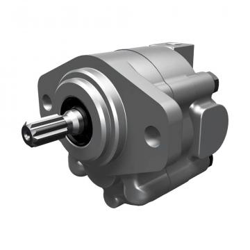
In the hydraulic pump, gear pump has the characteristics of simple structure, easy manufacture, small volume, low price, good self-priming ability, strong anti-pollution ability, etc. It is widely used in construction machinery, metallurgical machinery, mining machinery and other hydraulic equipment.
In order to make the gear pump continuously and smoothly absorb and drain oil, it is necessary to make the overlap coefficient of gear meshing more than 1 to ensure that at least one pair of gear teeth are engaged at any instant of continuous operation. Because of epsilon > 1, two pairs of gear teeth engage at the same time, that is, the original pair of meshing gear teeth have not yet come off, the latter pair of gear teeth have entered the meshing. This creates a closed dead volume between the 2 pairs of meshing teeth - trapped oil area. As the gear rotates, the volume of oil in the trapped area changes. When the closed volume decreases, the pressure rises sharply because the oil in the trapped area can not be discharged. As the gear continues to rotate, the closing volume increases gradually (the closing volume of a pair of meshing gear teeth in the suction chamber is the largest when they are about to be detached), and the trapped oil area forms a local vacuum due to the failure to fill the oil. Oil trapped in a trapped oil area is called trapped oil phenomenon because it has no place to discharge when it needs to be discharged and can not be replenished when it needs to be replenished.
According to the structure and sealing characteristics of the gear pump, the pump is only suitable for medium and low pressure systems. Therefore, the phenomenon of trapped oil in gear pump has great harm to its stability and reliability. In medium and low pressure systems, the oil compressibility is very small and can be omitted. The oil that is trapped in the trapped oil area will not cause any harm if it does not adapt to the change of elasticity.
(1) When the closed volume decreases, the oil in the trapped area is squeezed and forced out from the gap on the fitting surface of the parts, so that the gears, bushes and end caps are made.
(elastic side panels) and bearings are subjected to large additional loads (bending stress, shear stress and compressive stress, etc.). This kind of load, on the one hand, will make the oil temperature rise, causing power loss, reducing work efficiency; on the other hand, will make the parts worn, shorten the service life of the hydraulic pump.
(2) When the closed volume becomes larger, a local vacuum is formed in the trapped oil area, which causes the dissolved gas to be precipitated, gasified and formed bubbles. such
Bubble, on the one hand, will increase the noise of gear pump, produce cavitation and damage meshing accuracy, reduce work efficiency, shorten service life; on the other hand, it will cause system impact and vibration, resulting in pressure and flow pulsation.
When a pair of standard involute gears are installed correctly, the indexing circles of the two gears are tangent, so the pitch circle and the indexing circle coincide, and the meshing angle is equal to the pressure angle on the indexing circle. At this time, the center distance a is called the center distance or the standard center distance when the gears are installed correctly, and its value is a = M2 (z1 + Z 2). For the standard gear pump, the number of teeth of the two gears is the same. 1 = Z2 = z, a = m z; indexing circle tooth thickness is equal to the width of the groove, that is: S1 = E1 = Pi 2 m = S2 = e2, indicating that the standard gear pump installed correctly without backlash. In practical work, the actual center distance A'of the gear is larger than the standard center distance A' due to the design accuracy, manufacturing and installation requirements of the gear. So in the process of gear rotation, the meshing parameters of the gear change, that is, top clearance C'> cm *, meshing angle a'> a, pitch radius R'> R. Because of the change of meshing parameters, the clearance on the tooth side will increase, and the clearance will communicate with the closed volume close to the suction and drainage cavities respectively. Therefore, no matter how the dead volume changes, its interior is continuous in series, and its changing part of the cylindrical profile is perpendicular to the center distance of the two gears. Aiming at the locations and changing characteristics of oil trapping phenomenon of gear pump, we improved the structure of pump shell bottom, shaft sleeve and end cover (elastic side plate) along the closed dead volume (Fig. 1b) cylindrical center line, and installed a reservoir in the bottom structure space of pump shell, which can completely eliminate the harm of oil trapping of gear pump and improve the structure.
Improved design requirements:
(1) Machining 2.6 times the gear modulus along the center distance of the gear sleeve, the end cover or the elastic side plate, i.e. 2.6 m (symmetrical two-section tangent), 5 m M-6 m m wide, 4 m m-5 m m deep groove, and 5-6 m m to 6 m m deep groove at the center of the groove bottom until the trapped channel at the bottom of the pump shell;
(2) the trapped oil passage must be concentric with the threaded hole of the pump housing, and the flow resistance should be small.
(3) the accumulator can be of many kinds of structure, but its basic structure is suitable for the use of pouch accumulator.
(4) Because of the small change of trapped oil volume, the size of the reservoir should be as small as possible, and the connection strength with the bottom of the pump shell should be enough.
(5) a boss is designed at the center of the pump shell and hollowed out in the middle to meet the needs of installing the storage device.
(6) the storage device is designed to separate the oil and gas chambers, and the arc inside the cavity is excessive.
(7) Balloon rubber material should have good elasticity, and oil resistance, aging resistance, to adapt to the temperature range (-10 ~70
(8) the inflation (nitrogen) pressure of the accumulator is P0 inflated by 95% of the normal working pressure of the hydraulic pump P1.
(9) the oil and gas chamber of the storage tank must be tightly sealed at the threaded joint, so it is not allowed to leak.
(10) the storage device should be dismantled and installed conveniently. When it is installed at the bottom of the pump shell, the necessary protective cover should be installed.
(11) On the premise of satisfying the pulsation requirement of the hydraulic pump, in order to reduce the working frequency of the reservoir and discharger, the gear pump is designed by reducing the number of teeth, increasing the modulus and correcting the positive displacement (preventing undercutting) as far as possible.
Working characteristics after improvement
(1) the working frequency of the storage device is f = zn60 (Z: gear pump number; N: gear pump speed r/min);
(2) When the closed volume changes from large to small, the pressure oil enters the reservoir oil chamber through the trapped channel (at this time the air bag is compressed and contracted). When closing dead volume
The pressure oil in the reservoir oil chamber is added to the closed volume through the trapped oil passage when it becomes small and large (at this time, the air sac loses pressure and expands).
(3) under the ideal working condition, the maximum working pressure PA of the reservoir and discharger is slightly higher than the outlet pressure P1 of the hydraulic pump (which can be calculated by the formula of involute polar coordinates and the characteristic parameters of gears, the differential equation of the closed volume and the relevant formula of the accumulator). The minimum working pressure Pb is equal to the inlet pressure P2 of the hydraulic pump. Namely: PA >p1, Pb =p2;
(4) because of the high inflation pressure of the accumulator, the air bag has smaller shrinkage.
(5) eliminate the danger of hydraulic pump trapped oil and improve the volumetric efficiency and efficiency of hydraulic pump.
(6) improve the performance of the hydraulic pump and prolong the service life of the hydraulic pump.
(7) reduce the noise of the hydraulic pump and improve the working environment.


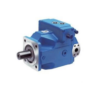 USA VICKERS Pump PVH131R13AF30B252000002001AB010A
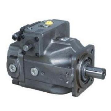 Parker Piston Pump 400481002108 PV140R1K1B4NWLZ+PGP517A0
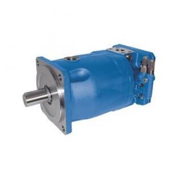 Parker Piston Pump 400481003286 PV180R1K1A4NYCD+PGP511A0
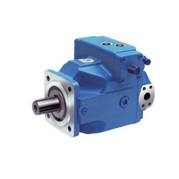 USA VICKERS Pump PVH057R02AA10B25200000100100010A
 Parker Piston Pump 400481004166 PV270R9K1B4NYLZK0033+PVA